LED-Matrix-Panelの駆動(3)
LED-Matrix-Panelに幾何模様のアニメーションを表示しました。
LED Matrix Panelで幾何模様のアニメーション
LED Matrix Panelの駆動(1), LED Matrix Panelの駆動(2)と同様の回路接続で、
幾何模様のアニメーションを作成しました。
例2、例3は、「Hari Fun」さんの作品を多少変更して使わせていただきました。
例1.簡単な直線のアニメーション
2本の直線を回転してみました。
1.完成動画です。
2.プログラムです。
#include <PxMatrix.h>

#define P_LAT 22
#define P_A 19
#define P_B 23
#define P_C 18
#define P_D 5
#define P_OE 2

hw_timer_t * timer = NULL;
portMUX_TYPE timerMux = portMUX_INITIALIZER_UNLOCKED;

// Pins for LED MATRIX
PxMATRIX display(64,32,P_LAT, P_OE,P_A,P_B,P_C,P_D);

int red1 = 0;
int green1 = 255;
int blue1 = 0;
int red2 = 255;
int green2 = 0;
int blue2 = 0;

void IRAM_ATTR display_updater() {
  portENTER_CRITICAL_ISR(&timerMux);
  display.display(70);
  portEXIT_CRITICAL_ISR(&timerMux);
}

void setup() {
  Serial.begin(9600);
  display.begin(16);

  timer = timerBegin(0, 80, true);
  timerAttachInterrupt(timer, &display_updater, true);
  timerAlarmWrite(timer, 2000, true);
  timerAlarmEnable(timer);

  delay(1000);
}

void loop() {
  for (int i=0; i<33; i++) {
    display.drawLine(i*2, 0, 64-i*2, 32, display.color565(red1,green1,blue1));
    display.drawLine(0, 32-i, 64, i, display.color565(red2,green2,blue2));
    delay(30);
    display.fillScreen(display.color565(0, 0,0));
  }

  for (int i=0; i<32; i++) {
    display.drawLine(i*2, 0, 64-i*2, 32, display.color565(red2,green2,blue2));
    display.drawLine(0, 32-i, 64, i, display.color565(red1,green1,blue1));
    delay(15);
    display.fillScreen(display.color565(0, 0,0));
  }

  red1 = random(8,32);
  green1 = random(8,64);
  blue1 = random(8,32);
  red2 = random(8,32);
  green2 = random(8,64);
  blue2 = random(8,32);
}
例2.円を使ったアニメーション
円がランダムな位置で発生し、大きくなっていきます。
1.完成動画です
2.プログラムです。
#include <PxMatrix.h>

// Pins for LED MATRIX
#define P_LAT 22
#define P_A 19
#define P_B 23
#define P_C 18
#define P_D 5
#define P_OE 2

hw_timer_t * timer = NULL;
portMUX_TYPE timerMux = portMUX_INITIALIZER_UNLOCKED;

PxMATRIX display(64,32,P_LAT,P_OE,P_A,P_B,P_C,P_D);

//== Circles ==
int width = 64;
int height = 32;
#include "Circle.h"
int dropRate = 500;
unsigned long timeToDrop;
int dropCount = -1;
const int dropMax = 3;
Circle *drops[dropMax];

void IRAM_ATTR display_updater() {
  portENTER_CRITICAL_ISR(&timerMux);
  display.display(70);
  portEXIT_CRITICAL_ISR(&timerMux);
}

void InitDrops() {
  for (int i=0; i<dropMax; i++) {
    drops[i] = new Circle(0,0,0,0);
  }
}

void DropAnother() {
  if (millis()>timeToDrop) {
    if (++dropCount>=dropMax) dropCount=0;
    Circle *aDrop = drops[dropCount];
    aDrop->x = random(0,width);
    aDrop->y = random(0,height);
    aDrop->r = 1;
    aDrop->c = display.color565(random(8,32), random(8,64), random(8,32));
    timeToDrop = millis() + dropRate;
  }
}

void AnimateCircles() {
  display.fillScreen(0);
  for (int i=0; i<dropMax; i++) {
    Circle aCircle = *(drops[i]);
    if (aCircle.r != 0) {
      display.drawCircle(aCircle.x, aCircle.y, aCircle.r, aCircle.c);
      drops[i]->r += 1;
    }
  }
  delay(10);
}

void setup() {
  Serial.begin(9600);
  display.begin(16);

  timer = timerBegin(0, 80, true);
  timerAttachInterrupt(timer, &display_updater, true);
  timerAlarmWrite(timer, 2000, true);
  timerAlarmEnable(timer);

  InitDrops();
}

void loop() {
  DropAnother();
  AnimateCircles();
}
ポインタの要素「 x 」と「 y 」はランダムな値を取得して円の中心とし、円の半径「 r 」を増加して円を大きくしています。
また、円の色 「 c 」もランダムな値を取得して変化させています。
ヘッダーファイル「Circle.h」です。
class Circle {
  public:
    Circle(int x_, int y_, int r_, uint16_t c_);
    int x;
    int y;
    int r;
    uint16_t c;
  private:
};

Circle::Circle(int x_, int y_, int r_, uint16_t c_)
{
  x = x_;
  y = y_;
  r = r_;
  c = c_;
}
例3.6角形のアニメーション
6角形の回転、拡大、縮小をしています。
1.完成動画です。
2.プログラムです。
#include <PxMatrix.h>

#define P_LAT 22
#define P_A 19
#define P_B 23
#define P_C 18
#define P_D 5
#define P_OE 2

hw_timer_t * timer = NULL;
portMUX_TYPE timerMux = portMUX_INITIALIZER_UNLOCKED;

// Pins for LED MATRIX
PxMATRIX display(64,32,P_LAT, P_OE,P_A,P_B,P_C,P_D);

int red = 0;
int green = 255;
int blue = 0;

void IRAM_ATTR display_updater() {
  portENTER_CRITICAL_ISR(&timerMux);
  display.display(70);
  portEXIT_CRITICAL_ISR(&timerMux);
}

void setup() {
  Serial.begin(9600);
  display.begin(16);

  timer = timerBegin(0, 80, true);
  timerAttachInterrupt(timer, &display_updater, true);
  timerAlarmWrite(timer, 2000, true);
  timerAlarmEnable(timer);

  delay(1000);
}

void Chord(int r, float rot) {
  int nodes = 6;
  float x[nodes];
  float y[nodes];

  for (int i=0; i<nodes; i++) {
    float a = rot + (PI*2*i/nodes);
    x[i] = 31+3 + cos(a)*r;
    y[i] = 16 + sin(a)*r;
  }

  display.fillScreen(display.color565(0, 0,0));
  for (int i=0; i<(nodes-1); i++) {
    for (int j=i+1; j<nodes; j++) {
      display.drawLine(x[i],y[i], x[j],y[j], display.color565(red, green,blue));
    }
  }
}

void loop() {
  float rot;
  float rotationSpeed = PI/15;
  for (int r=1; r<44; r+=3) {
    Chord(r, rot+=rotationSpeed);
    delay(50);
  }

  for (int r=1; r<44; r+=3) {
    Chord(44-r, rot-=rotationSpeed);
    delay(30);
  }
  red = random(8,32);
  green = random(8,64);
  blue = random(8,32);
}
3.プログラムは、下図のようにラインを引いて6角形を作成し、大きさ、回転角度、色を変化させています。
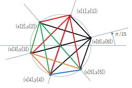
黒線の部分 (x[0],y[0])⇒(x[0],y[0]), (x[0],y[0])⇒(x[1],y[1]), (x[0],y[0])⇒(x[2],y[2]), (x[0],y[0])⇒(x[3],y[3]),
(x[0],y[0])⇒(x[4],y[4]), (x[0],y[0])⇒(x[5],y[5]) の5本。
赤線の部分 x[1],y[1])⇒(x[2],y[2]), (x[1],y[1])⇒(x[3],y[3]), (x[1],y[1])⇒(x[4],y[4]), (x[1],y[1])⇒(x[5],y[5]) の4本
緑線の部分 x[2],y[2])⇒(x[3],y[3]), (x[2],y[2])⇒(x[4],y[4]), (x[2],y[2])⇒(x[5],y[5]) の3本
橙線の部分 x[3],y[3])⇒(x[4],y[4]), (x[3],y[3])⇒(x[5],y[5]) の2本
青線の部分 x[4],y[4])⇒(x[5],y[5]) の1本
です。